- 您现在的位置:买卖IC网 > Sheet目录308 > ADUM5201CRWZ (Analog Devices Inc)IC DGTL ISOLATOR W/DC-DC 16SOIC
Data Sheet
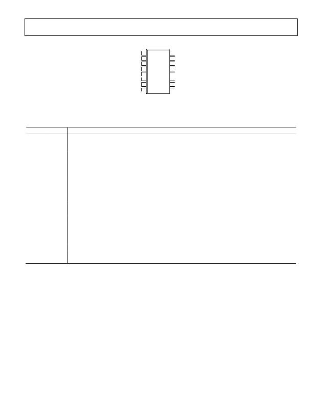
ADuM5200/ADuM5201/ADuM5202
V DD1 1
GND 1 2
16
15
V ISO
GND ISO
V IA 3
ADuM5201
14
V OA
V OB 4
TOP VIEW
13 V IB
RC IN 5
(Not to Scale) 12 NC
RC SEL 6
V E1 7
GND 1 8
11
10
9
V SEL
V E2
GND ISO
NC = NO CONNECT
Figure 7. ADuM5201 Pin Configuration
Table 22. ADuM5201 Pin Function Descriptions
Pin No. Mnemonic Description
1
2, 8
3
4
5
6
7
9, 15
10
11
12
13
14
16
V DD1
GND 1
V IA
V OB
RC IN
RC SEL
V E1
GND ISO
V E2
V SEL
NC
V IB
V OA
V ISO
Primary Supply Voltage, 3.0 V to 5.5 V.
Ground 1. Ground reference for isolator primary side. Pin 2 and Pin 8 are internally connected to each other, and it is
recommended that both pins be connected to a common ground.
Logic Input A.
Logic Output B.
Regulation Control Input. This pin must be connected to the RC OUT pin of a master iso Power device or tied low. Note
that this pin must not be tied high if RC SEL is low; this combination causes excessive voltage on the secondary side,
damaging the ADuM5201 and possibly the devices that it powers.
Control Input. Determines self-regulation mode (RC SEL high) or slave mode (RC SEL low), allowing external regulation.
This pin is weakly pulled to the high state. In noisy environments, tie this pin either high or low.
Data Enable Input. When this pin is high or not connected, the primary output is active; when this pin is low, the
output is in a high-Z state.
Ground Reference for Isolator Side 2. Pin 9 and Pin 15 are internally connected to each other, and it is recommended
that both pins be connected to a common ground.
Data Enable Input. When this pin is high or not connected, the secondary output is active; when this pin is low, the
output is in a high-Z state.
Output Voltage Selection. When V SEL = V ISO , the V ISO setpoint is 5.0 V. When V SEL = GND ISO , the V ISO setpoint is 3.3 V.
In slave regulation mode, this pin has no function.
No Internal Connection.
Logic Input B.
Logic Output A.
Secondary Supply Voltage. Output for secondary side isolated data channels and external loads.
Rev. B | Page 13 of 28
发布紧急采购,3分钟左右您将得到回复。
相关PDF资料
ADUM5230ARWZ-RL
IC ISOLATOR 2CH HBRIDGE 16-SOIC
ADUM5240ARZ-RL7
IC ISOLATOR 2CH W/CONV 8-SOIC
ADUM5400CRWZ-RL
IC ISOLATOR 4CH DCDC CONV 16SOIC
ADUM5402WCRWZ
IC ISOLATOR 4CH DCDC CONV 16SOIC
ADUM5404CRWZ
IC ISOLATOR 4CH DCDC CONV 16SOIC
ADUM6132ARWZ-RL
IC GATE DRIVER ISOLATED 16-SOIC
ADUM6201CRIZ
ISOLATED DC-DC CONV 2CH 16SOIC
ADUM6404ARWZ
IC ISOLATOR 4CH DCDC CONV 16SOIC
相关代理商/技术参数
ADUM5201CRWZ1
制造商:AD 制造商全称:Analog Devices 功能描述:Dual-Channel Isolators with Integrated DC/DC Converter
ADUM5201CRWZ2
制造商:AD 制造商全称:Analog Devices 功能描述:Dual-Channel Isolators with Integrated DC/DC Converter
ADUM5201CRWZ-RL
功能描述:IC DIG ISOLATOR W/DC-DC 16SOIC RoHS:是 类别:隔离器 >> 数字隔离器 系列:IsoPower®, iCoupler® 产品培训模块:IsoLoop® Isolator 标准包装:50 系列:IsoLoop® 输入 - 1 侧/2 侧:5/0 通道数:5 电源电压:3 V ~ 5.5 V 电压 - 隔离:2500Vrms 数据速率:110Mbps 传输延迟:12ns 输出类型:CMOS 封装/外壳:16-SOIC(0.154",3.90mm 宽) 供应商设备封装:16-SOIC N 包装:管件 工作温度:-40°C ~ 85°C 其它名称:390-1053-5
ADUM5201WCRWZ
制造商:Analog Devices 功能描述:AUTO 2-CHANNEL ISO W/INTEGRATE 制造商:Analog Devices 功能描述:AUTO 2-CHANNEL ISO W/INTEGRATED DC/DC - Rail/Tube 制造商:Analog Devices 功能描述:ISOLATOR DGTL W/DC-DC 16SOIC
ADUM5201WCRWZ-RL
制造商:Analog Devices 功能描述:AUTO 2-CHANNEL ISO W/INTEGRATE 制造商:Analog Devices 功能描述:AUTO 2-CHANNEL ISO W/INTEGRATED DC/DC - Tape and Reel 制造商:Analog Devices 功能描述:IC DGTL ISOLATOR W/DC-DC 16SOIC
ADUM5202
制造商:AD 制造商全称:Analog Devices 功能描述:Dual-Channel Isolators with Integrated DC/DC Converter
ADUM5202ARWZ
功能描述:IC DGTL ISOLATOR W/DC-DC 16SOIC RoHS:是 类别:隔离器 >> 数字隔离器 系列:IsoPower®, iCoupler® 产品培训模块:IsoLoop® Isolator 标准包装:50 系列:IsoLoop® 输入 - 1 侧/2 侧:5/0 通道数:5 电源电压:3 V ~ 5.5 V 电压 - 隔离:2500Vrms 数据速率:110Mbps 传输延迟:12ns 输出类型:CMOS 封装/外壳:16-SOIC(0.154",3.90mm 宽) 供应商设备封装:16-SOIC N 包装:管件 工作温度:-40°C ~ 85°C 其它名称:390-1053-5
ADUM5202ARWZ1
制造商:AD 制造商全称:Analog Devices 功能描述:Dual-Channel Isolators with Integrated DC/DC Converter
